
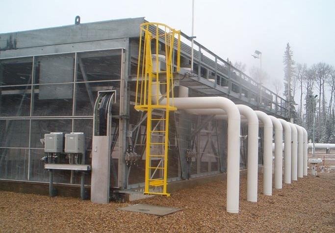
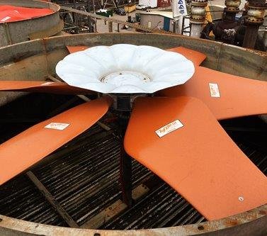
Air Cooled Heat Exchangers
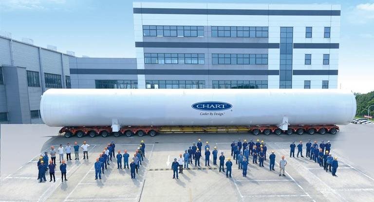
Through the Hudson Products, Air-X-Changers, Smithco, Hammco and Cooler Service Company brands, Chart has brought together trusted leaders to provide heat transfer solutions across upstream, midstream, downstream, refinery, petrochemicals, power and others.


-1134x670.jpg)


.jpg?ext=.jpg)


 Request A Quote
 Email An Inquiry
 Find Our Locations
 Join Our Team